3rd Laboratory Session ~1 meeting
A thermistor is a special type of resistor whose resistance is very temperature dependent (THERMal - resISTOR). Thermistors are used in various ways such as temperature sensors, inrush current limiters and self-resetting overcurrent protectors. Electrical power dissipated on thermistor heats up the device and thus changes its electrical properties (resistance). In thermistor Spice model, the temperature has to be modelled by some electrical value, e.g. voltage. We will inspect a thermistor model with build-in temperature modeling. We will simulate a thermistor circuit and analyse its properties.
Thermistor modelling
There are two basic types of thermistors:
- NTC (resistance decreases as temperature rises - "negative temperature coefficient") and
- PTC (resistance increases as temperature rises - "positive temperature coefficient"). We will model the first type (NTC) in this session.
Resistance changes over temperature are usually not linear in a NTC thermistor. Manufacturers often characterizes NTCs using Steinhart–Hart equation. Its simplified version is given below:
A NTC thermistor has a nominal resistance of R0 at temperature T0. Resistance at temperature T is R(T). Every NTC also has a special property β, which is measured and given by NTC thermistor manufacturer (we usually find it in product datasheet, for example this one (or another one)).
At first, we will create a subcircuit that will model our NTC thermistor. For this subcircuit the temperature will be one of the input parameters. Rememeber - we have to calculate the NTC resistance using a formula. We learned in previous session, how to tell SpiceOpus to calculate the parameter value, instead of interpret it (we use curly brackets, for ex.: "r={...}").
We will do some nasty tricks in this subckt, that will help us fully model our NTC at the end. The first one is this: we will not use element R to model the resistivity, but rather use a special element, called "nonlinear controlled source". As the name tells, we can use an expression to model a node voltage (or branch current). The following line encodes a nonlinear controled source (has to start with b, that will simulate resistance (its numerical value) between nodes r and 0.
br (r 0) v={r0}*exp({b}/({temp}+273) - {b}/(25+273))
Once we have a numerical value of thermistor resistivity, we can read it from the node r, with v(r,0). Now, if we want to include this thermistor subcircuit to another circuit, it has to look like a two-pole element from the outside. Another thing - some circuit will apply some voltage between the thermistor terminals - this means, our thermistor has to "produce" electrical current, that applies to applied voltage (considering, of course, parameters e.g.: temperature). So, we need to place a current source between the thermistor terminals. You can of course use a nonlinear controled source you just learned about, like this (current is voltage vs. resistance):
bl (2 n) i=v(p,n)/v(r)
Now your netlist probably looks something like this:
.subckt ntc p n param: temp=25 b=3988 r0=4700
vi (p 2) dc=0
bl (2 n) i=v(p,n)/v(r)
br (r 0) v={r0}*exp({b}/({temp}+273) - {b}/(25+273))
.ends
Now you are able to model just anything in Spice, as long as you have an equation for it.
Thermistor self-heating
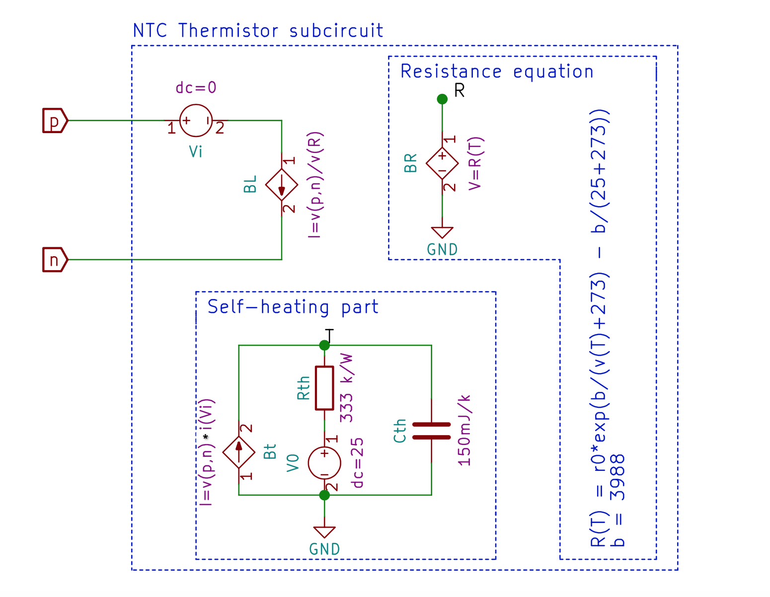
Power dissipation of the NTC causes the same element to heat-itself-up (!) - so its resistance changes again! We improve the model in such manner, that input parameter temp is no-longer needed, but is calculated during the transient analysis. The self-heating part is a circuit which models the temperature change (the temperature is represented by the node T voltage!). The current in this circuit actually represents dissipated power (v(p,n)*i(Vi)). The independent voltage source represents the initial temperature (25 degrees C). There are also thermal resistance and thermal capacity, which are properties of NTC body and environment. Using this configuration we will model changes in NTC resistance during time, when pulses are applied to the NTC.
This is the file we created during the session: